Part 1
The basics
What is CNC? What are the various types of machines available? What are the key advantages and disadvantages associated with them?
Part 2
Design for CNc machining
In under 15 minutes, you will acquire the knowledge to create components that are optimized for CNC machining.
Part 3
Materials for CNCmachining
Discover further information regarding the commonly utilized materials and finishes in CNC machining.
Part 4

Cost reduction tips
Utilize the following three design recommendations to reduce the expenses associated with your CNC machining endeavor.
Part 5
Start CNC machining
Learn how to prepare, get a quote &source custom CNC machined parts in 3simple steps.
Part 6
Useful resources
A compilation of valuable sources for individuals seeking to explore further.
Part 1
The basics
What is CNC machining?
CNC machining utilizes subtractive manufacturing techniques to produce parts by cutting away material from a solid block, known as the blank or workpiece, with a range of cutting tools.
This manufacturing approach is fundamentally distinct from additive (3D printing) or formative (Injection Molding) technologies. The mechanisms involved in material removal greatly impact the advantages, constraints, and design limitations of CNC. Further details will be discussed below.

CNC machining represents a digital manufacturing process that yields precise components boasting superior physical characteristics straight from a CAD file. Thanks to its advanced automation, CNC offers cost-effective solutions for individualized custom parts as well as moderate-volume manufacturing.
Virtually all types of materials are suitable for CNC machining. Some of the most frequently used materials are metals like aluminum and steel alloys, as well as plastics such as ABS, Delrin, and Nylon. Additionally, foam, composites, and wood can also be machined.
The fundamental CNC procedure consists of three main stages. Initially, the engineer creates a CAD model of the part. Subsequently, the machinist converts the CAD file into a CNC program (G-code) and prepares the machine for operation. Lastly, the CNC system autonomously carries out all machining tasks, eliminating material and producing the final part.
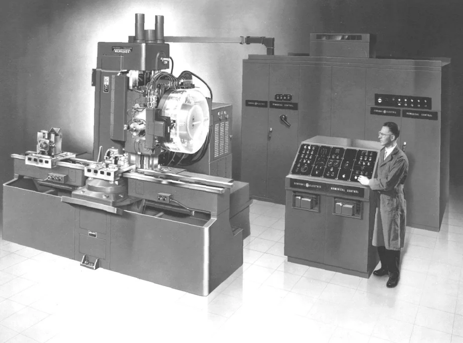
A brief history of CNC machining
- The bowl, which was crafted using a lathe, is the earliest machined object ever unearthed. It was discovered in Italy and dates back to 700 B.C.
- The automation of machining was first attempted in the 18th century, with machines that were solely mechanical and operated using steam power.
- The initial programmable device was created at MIT in the late 1940s, utilizing punched cards to encode every single movement.
- The expansion of computers during the 1950s and 1960s introduced the “C” in CNC and brought about a significant transformation in the manufacturing sector.
- Nowadays, CNC machines have evolved into sophisticated robotic systems equipped with multi-axis and multi-tooling capabilities.
Types of CNC machines
In this manual, our main emphasis will be on CNC machines that utilize cutting tools to eliminate material. These machines are widely used and offer a vast array of applications. Additionally, there are other types of CNC machines available such as laser cutters, plasma cutters, and EDM machines.
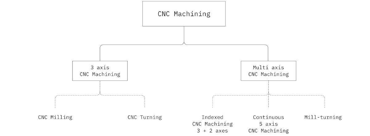
3-axis CNC machines
CNC milling and CNC turning machines exemplify 3-axis CNC systems. These fundamental machines facilitate the movement of the cutting tool along three linear axes in relation to the workpiece (horizontal, vertical, and depth-wise).
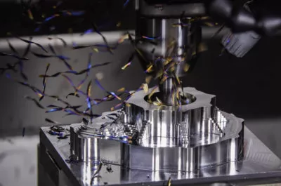
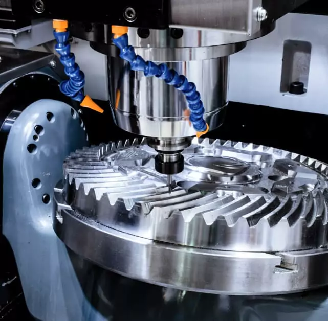
CNC milling
- The workpiece remains fixed in place either on the machine bed or within a vice.
- Cutting tools or drills rotating at high speed are utilized to eliminate material from the workpiece.
- The tools are connected to a spindle, which has the ability to move along three linear axes.
3-axis CNC milling machines are widely used due to their ability to create a variety of common geometries. These machines are user-friendly in terms of programming and operation, resulting in lower start-up machining expenses.
CNC milling may face limitations in tool access due to the three axes available for work. In some cases, certain areas may be difficult to reach. While this may not pose a significant problem for workpieces requiring only one rotation, multiple rotations can lead to a rapid escalation in labor and machining costs.
Can produce most parts with simple geometries.
High accuracy & tight tolerances.
Tool access & workholding design restrictions apply.
Manual repositioning of the workpiece lowers the achievable accuracy.

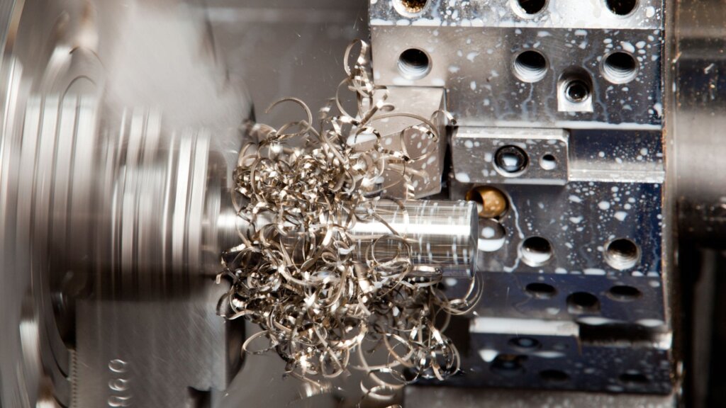
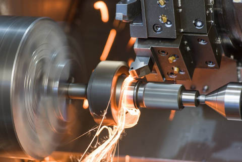
CNC turning (lathes)
- The workpiece is securely fastened to the spindle and rotates at a high velocity.
- A cutting implement or center drill follows the external or internal boundary of the component, shaping the structure.
- The instrument remains stationary and travels in polar directions (radially and longitudinally).
CNC lathes are widely utilized due to their ability to manufacture parts more quickly and cost-effectively compared to CNC mills, making them particularly advantageous for high-volume production.
CNC lathes are primarily limited to manufacturing components with a cylindrical shape, such as screws or washers. However, to surpass this constraint, the characteristics of the part are frequently CNC milled in a distinct machining process. Another option is to employ 5-axis mill-turning CNC centers, which can create the identical geometry in a single step.
Our CNC machining operations offer the most competitive pricing per part compared to all other alternatives.
Capable of manufacturing a wide range of components with uncomplicated shapes.
Only capable of manufacturing components with rotational symmetry and basic geometries.

5-axis CNC machining
There are three different types of multi-axis CNC machining centers available: 5-axis indexed CNC milling, continuous 5-axis CNC milling, and mill-turning centers equipped with live tooling.
The systems in question are essentially milling machines or lathes that have been improved with extra degrees of freedom. For instance, 5-axis CNC milling centers enable the machine bed or the toolhead (or both) to rotate, in addition to the three linear axes of movement.
The enhanced functionalities of these devices result in higher expenses. They necessitate specialized equipment and skilled operators. When it comes to intricate or topology optimized metal components, 3D printing is often the more appropriate choice.
Indexed 5-axis CNC milling
- The cutting tool is restricted to movement along three linear axes during machining.
- The bed and the toolhead have the ability to rotate between operations, allowing for access to the workpiece from various angles.
Indexed 5-axis CNC milling systems are commonly referred to as 3+2 CNC milling machines. This nomenclature stems from their utilization of the two extra degrees of freedom solely during machining operations for workpiece rotation.
These systems offer a significant advantage by removing the necessity for manual repositioning of the workpiece. As a result, components with intricate geometries can be produced more efficiently and with greater precision compared to a 3-axis CNC mill. However, they do not possess the full freeform capabilities of continuous 5-axis CNC machines.
Removes the necessity for manual readjustment.
Manufactures components with characteristics that are not aligned with a primary axis to a greater degree of precision.
The cost is higher compared to 3-axis CNC machining.
It is challenging to create highly precise contoured surfaces.
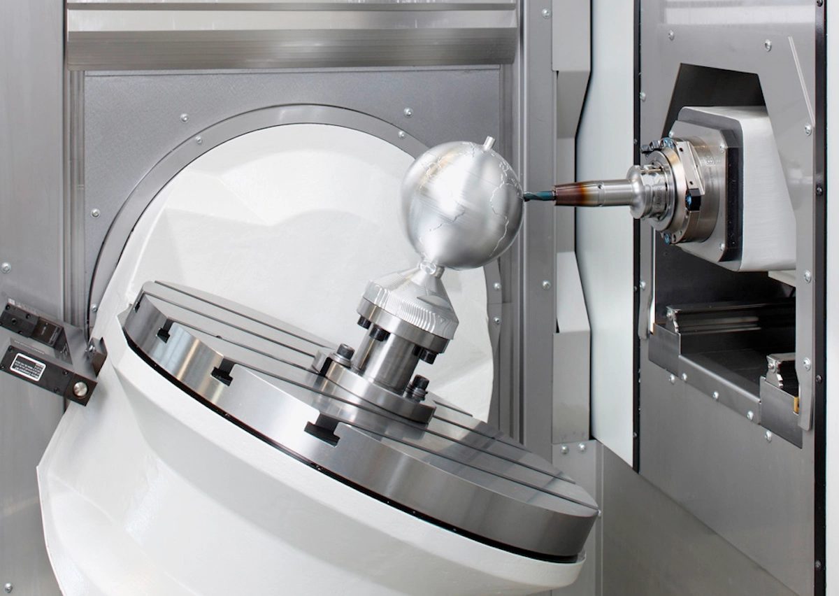
Continuous 5-axis CNC milling
- The cutting instrument has the capability to travel across three linear and two rotational axes in relation to the workpiece.
- During all machining operations, all five axes have the capability to move simultaneously.
5-axis CNC milling systems with continuous movement have a machine architecture that closely resembles that of indexed 5-axis CNC milling machines. This design enables the simultaneous movement of all five axes throughout the entire machining process.
In this manner, it becomes feasible to fabricate components with intricate, “natural” shapes that cannot be produced with the same level of precision using alternative techniques. However, these sophisticated functionalities undoubtedly entail a substantial expense, as it necessitates both costly equipment and skilled operators.
The manufacturing process enables the production of intricate components with an unparalleled level of precision.
Creates exceptionally sleek ‘organic’ finishes with minimal signs of machining.
Most expensive per unit among all CNC machining processes.
Restrictions on tool access remain in effect.
Mill-turning CNC centers
- The workpiece is affixed to a spindle that has the capability to either rotate at a high velocity, similar to a lathe, or position it at an exact angle, resembling a 5-axis CNC mill.
- Lathe and milling cutting tools are employed for the purpose of eliminating material from the workpiece, thereby shaping the component.
Mill-turning CNC centers are essentially CNC lathe machines that come with CNC milling tools. Swiss-style lathes, a variation of mill-turning centers, are known for their higher precision levels.
Mill-turn systems combine the efficiency of CNC turning with the versatility of CNC milling, making them perfect for producing components with rotational symmetry, such as camshafts and impellers, at a reduced expense compared to alternative 5-axis CNC machines.
The most affordable option among all the 5-axis CNC machining systems available.
The ability to achieve high production capabilities and enjoy design freedom is paramount.
Tool access limitations continue to be in effect.
Ideal for components with a circular shape.
To summarize
- 3-axis CNC milling machines produce components with basic shapes with high precision and cost-effectively.
- CNC lathes offer the most economical cost per unit, however, they are exclusively appropriate for part geometries that possess rotational symmetry.
- 5-axis CNC milling machines with indexing capabilities produce components that possess intricate features that are not aligned with the primary axes. These machines are capable of swiftly and precisely manufacturing such parts with exceptional accuracy.
- 5-axis CNC milling machines continuously produce components with intricate, ‘organic’ shapes and seamless curves, albeit at a premium price.
- Mill-turn CNC machines integrate the advantages of both CNC turning and CNC milling, offering a cost-effective solution for producing intricate components compared to traditional 5-axis CNC systems.
Benefits & Limitations of CNC machining
Below is a compilation of the primary advantages and drawbacks associated with CNC machining. Utilize this information to aid in determining if this technology aligns with your specific requirements.
Benefits of CNC machining
Limitations of CNC machining
Applications of CNC machining
CNC machining has proven to be incredibly versatile, with a multitude of applications developed over time.
We have gathered a selection of recent instances to demonstrate how experts have effectively utilized CNC machining to achieve optimal outcomes in various industrial scenarios. Utilize these examples as a source of inspiration for your own projects.
Space
CNC machining stands out as a highly suitable manufacturing process for producing components for space applications. This is not only because CNC parts exhibit exceptional precision and material characteristics, but also due to the extensive array of surface treatments that can be implemented on the machined parts. An illustrative instance is the utilization of CNC machining and space grade materials by KEPLER, enabling them to transform a mere sketch on a napkin into a fully functional satellite within a span of 12 months.
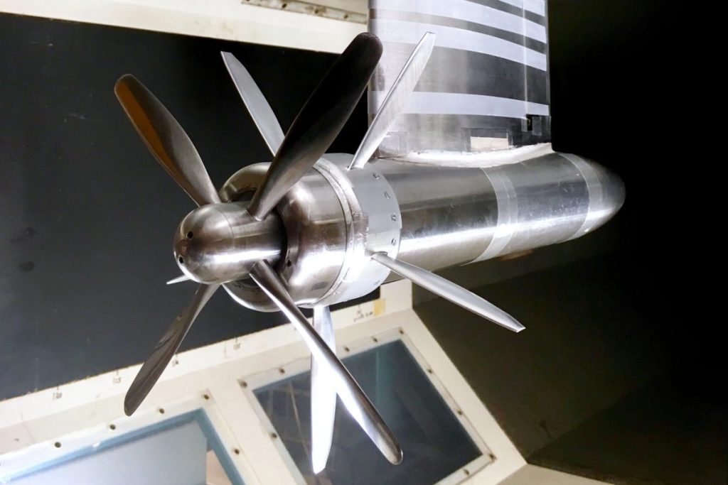
Aerospace
The aerospace sector was among the pioneers in adopting CNC machining due to its capacity to produce lightweight components with superior physical characteristics and precise tolerances. CNC machining is utilized in the production of aircraft parts as well as in the developmental phases.
An instance of this is Tomas Sinnige, a PhD researcher affiliated with the Delft University of Technology. Together with his research team, they employed CNC machining techniques to produce smaller models of their prototype engine, with the goal of enhancing the effectiveness of contemporary propeller engines.
Automotive
CNC machining finds its applications in the automotive sector for the production of custom parts that demand high performance.
During the developmental phases, PAL-V, a Dutch company, opted for CNC machining to produce and prototype crucial components for their groundbreaking Personal Air and Land Vehicles, which are essentially the pioneering flying cars globally.

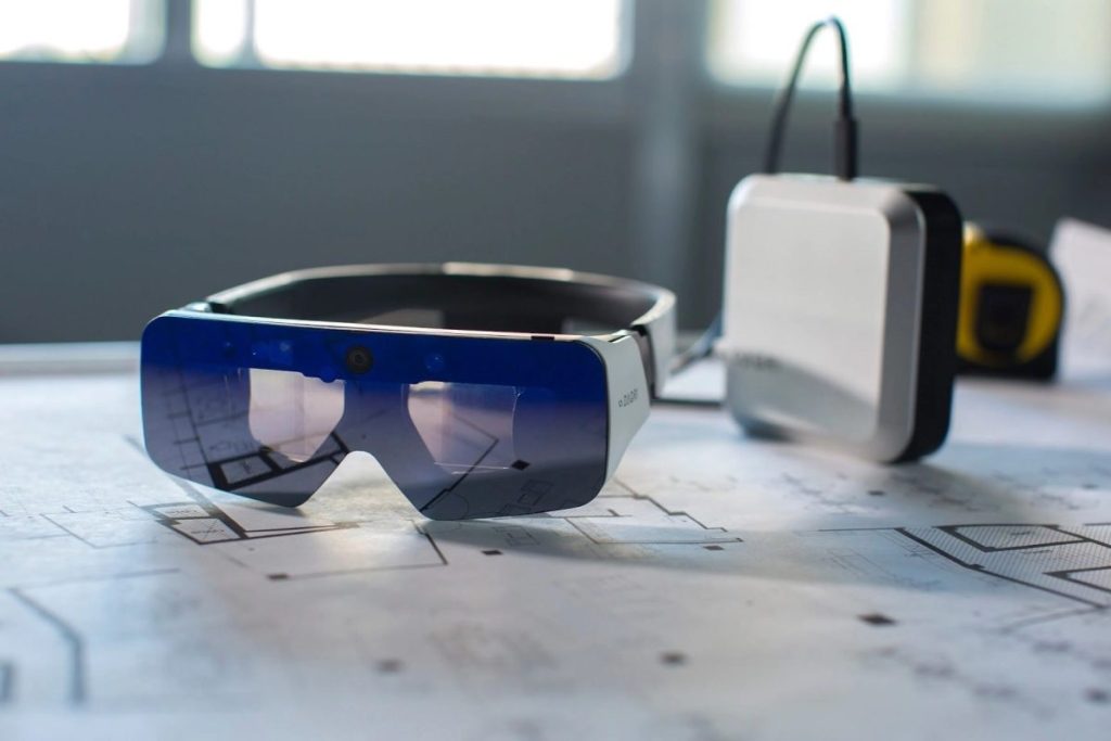
Product Design & Development
CNC machining is a highly appealing option for creating functional prototypes due to its capability to rapidly produce custom metal parts with excellent dimensional precision. This becomes crucial in the advanced phases of design and development.
The DAQRI design team, for instance, utilized CNC machining to prototype their professional Augmented Reality (AR) hardware. This manufacturing process was chosen for its cost-effectiveness and capability to produce custom metal parts with the necessary level of detail at the small scale required for their designs.
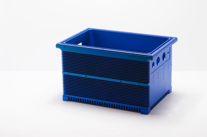
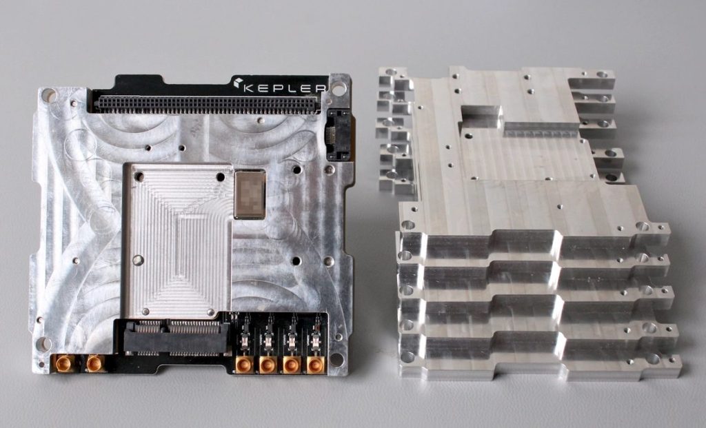
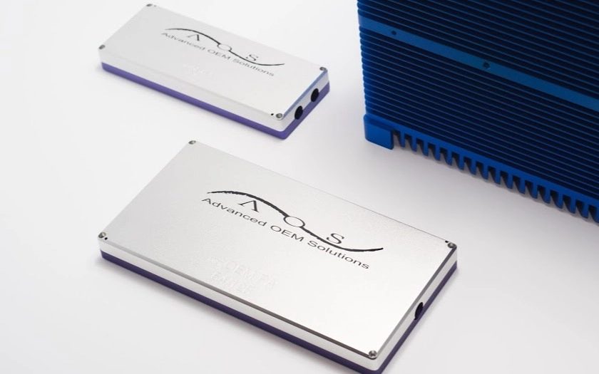
Electrical & electronic manufacturing
CNC machining finds extensive utility in the electrical and electronic manufacturing sector, encompassing a wide range of applications. These include the prototyping of PCBs as well as the production of enclosures.
For instance, TPAC utilized CNC machining to produce a casing for their high-power electronic sensing systems. The primary design considerations in this scenario were heat dissipation and electrical insulation. Therefore, CNC machined anodized aluminum proved to be the perfect choice for their unique custom enclosure.
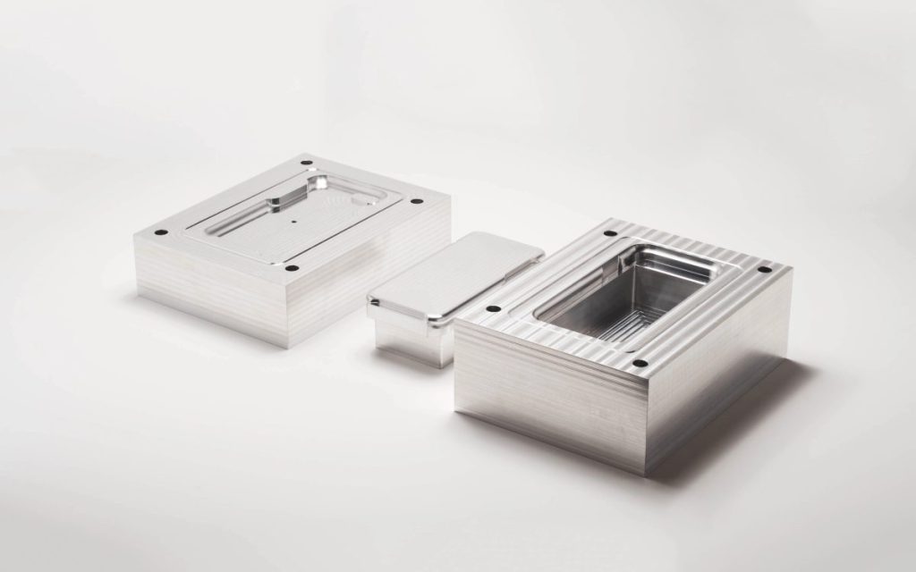
Tooling & Industrial manufacturing
One common industrial use of CNC machining involves creating tooling for various processes. For instance, molds used in Injection Molding are often CNC machined from aluminum or tool steel.
Precious Plastic, for example, created a solution for emerging markets that transforms discarded plastic into iPhone cases! To achieve this, they utilized an affordable manual injection molder and tailor-made CNC machined molds.
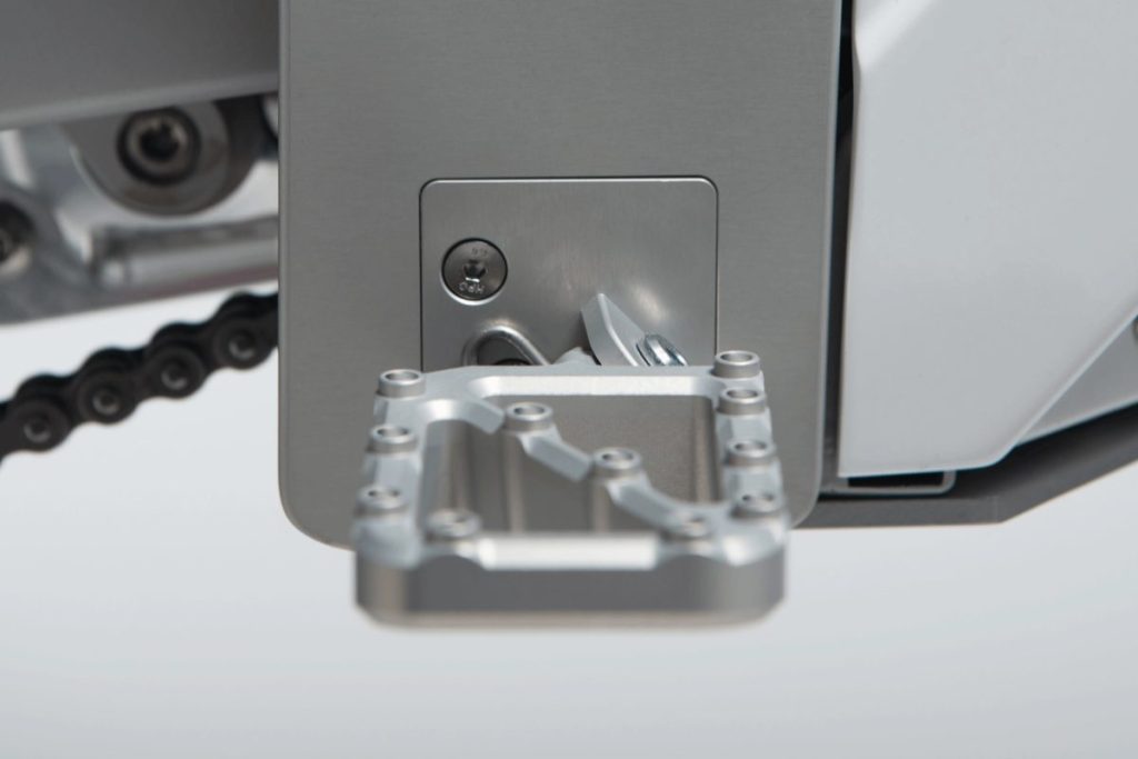
Sports & motorsports equipment
Manufacturers in the high-performance sports and motorsports industry constantly strive to enhance the performance of their products through weight reduction.
CAKE is a Swedish corporation that created and produced the initial off-road electric motorcycle. As the pioneer in its category, each part of the motorcycle was individually crafted using CNC technology to ensure the desired standard of excellence and longevity.
CNC machining vs. 3D printing
CNC machining and 3D printing are both valuable resources for engineers, each offering distinct advantages that cater to specific needs.
There are several straightforward principles that can be applied to the decision-making process when selecting between CNC machining and 3D printing.
Typically, components with straightforward shapes that can be easily produced using subtractive methods should be manufactured using CNC machining, particularly for metal parts.
Opting for 3D printing instead of CNC machining is a logical choice when you require:
- A low-cost plastic prototype
- Parts with very complex geometry
- A turnaround time of 2-5 days
- Speciality materials
Scaling up production
For large quantities (1,000’s or more), CNC machining and 3D printing are not recommended. Instead, forming technologies like investment casting or injection molding are more cost-effective due to economies of scale.
Please refer to the table below for quick access. In this simplification, it is assumed that all technologies have the capability to produce the geometry of the part in question. If this is not the case, 3D printing is typically the preferred manufacturing method.
| No. of Parts | Plastic | Metal |
|---|---|---|
| 1-10 | 3D printing | CNC machining (consider 3D printing) |
| 10-100 | 3D printing and CNC machining | CNC machining |
| 100-1000 | CNC machining (consider Injection molding) | CNC machining (consider Investment casting) |
| 1000+ | Injection molding | Investment or Die casting |
Part 2
Design for CNC machining
CNC machining design restrictions
The constraints in CNC machining design arise directly from the mechanics associated with the cutting process, namely:
Tool geometry
Most CNC machining cutting tools typically possess a cylindrical form, featuring either a flat or spherical end. This design limitation imposes restrictions on the range of part geometries that can be manufactured.
For example, the internal vertical corners of a CNC part will consistently feature a radius, regardless of the size of the cutting tool utilized.
Tool access
CNC machining is not possible for surfaces that the cutting tool cannot reach.
For instance, this rule restricts the production of components containing concealed internal geometries and imposes a constraint on the maximum depth of an undercut.
Workpiece stiffness
The workpiece may deform or vibrate as a result of the cutting forces and high temperatures generated during the machining process.
For instance, this constraint restricts the minimum wall thickness achievable for a CNC machined component and the maximum aspect ratio of taller attributes.
Tool stiffness
During the machining process, similar to the workpiece, the cutting tool may also experience deflection or vibration. As a consequence, the tolerances become less precise and there is even a risk of the tool breaking.
The prominence of the effect intensifies as the length-to-diameter ratio of the cutting tool increases, thereby making it challenging to CNC machine deep cavities.

Workholding
The configuration of a component dictates how it will be secured on the CNC machine and the quantity of setups needed. This not only affects the expenses involved but also the precision of the component.
An illustration of this is how manual repositioning can lead to a minor, yet significant, positional discrepancy. This stands as a major advantage of 5-axis over 3-axis CNC machining.
Design rules for CNC machining
In the provided table, we outline the manner in which these limitations are transformed into practical guidelines for design.
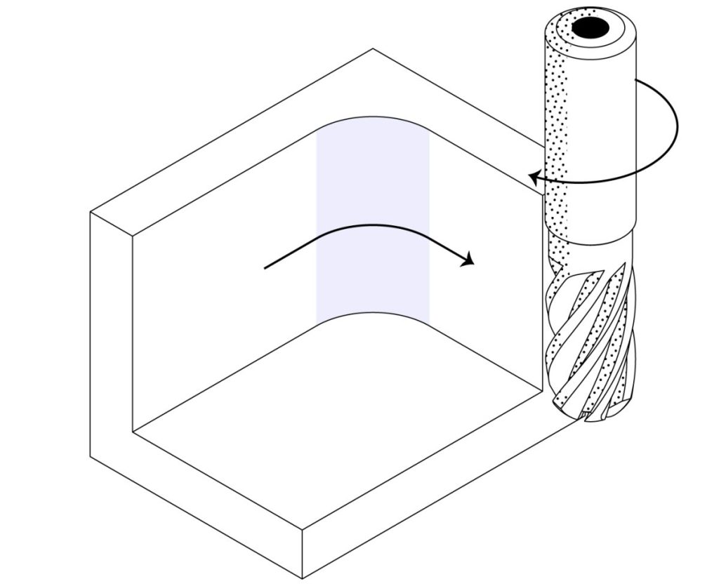
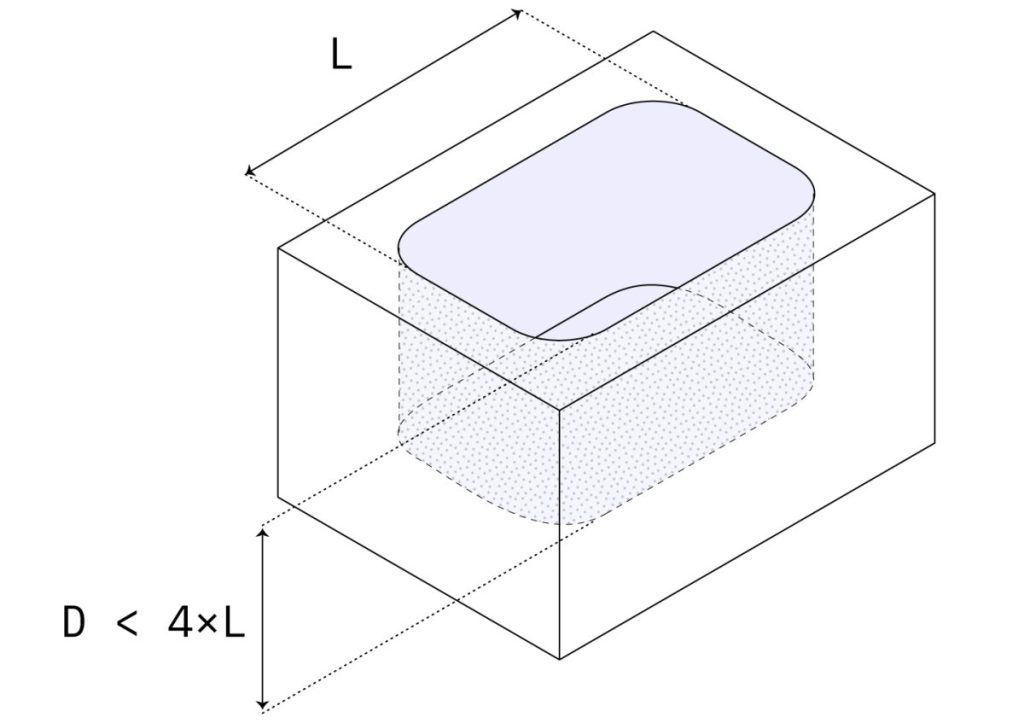
Cavities & pockets
Recommended depth: 4 x cavity width
Feasible depth: 10 x tool diameter or 25 cm (10’’)
Cutting tools with a larger diameter are required to machine deeper cavities, which in turn impacts the fillets of the internal edges.
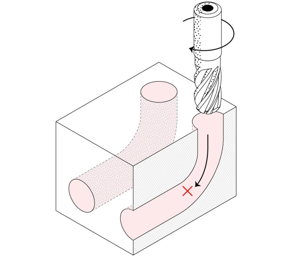
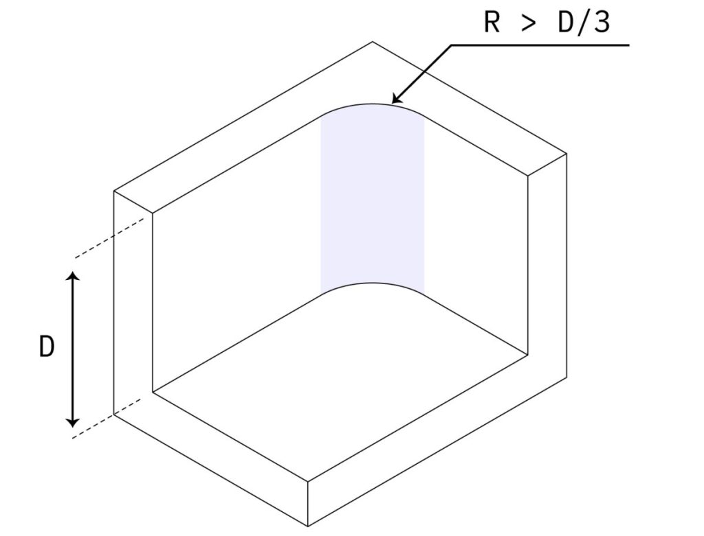
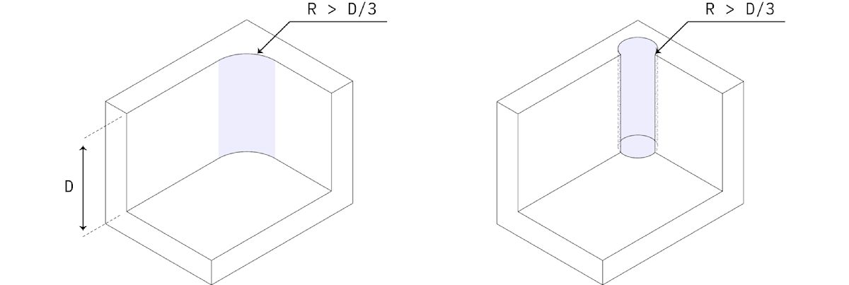
Internal edges
Recommended: larger than ⅓ x cavity depth
A larger fillet is more beneficial for internal vertical edges.
The edges located on the floor of a cavity must be either sharp or possess a radius of either 0.1 mm or 1 mm.
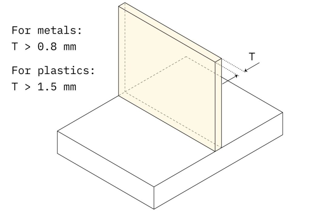
Minimum wall thickness
Recommended: 0.8 mm (for metals)
Feasible: 0.5 mm
Recommended: 1.5 mm (for plastics)
Feasible: 1.0 mm
Reducing the thickness of the wall diminishes the rigidity of the workpiece, leading to amplified vibrations and decreased attainable tolerances.
Plastics are particularly susceptible to warping and thermal softening, therefore requiring a greater minimum wall thickness.
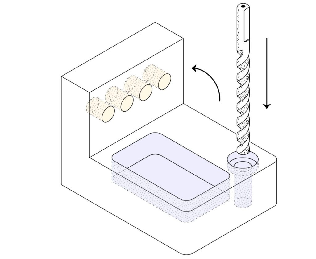
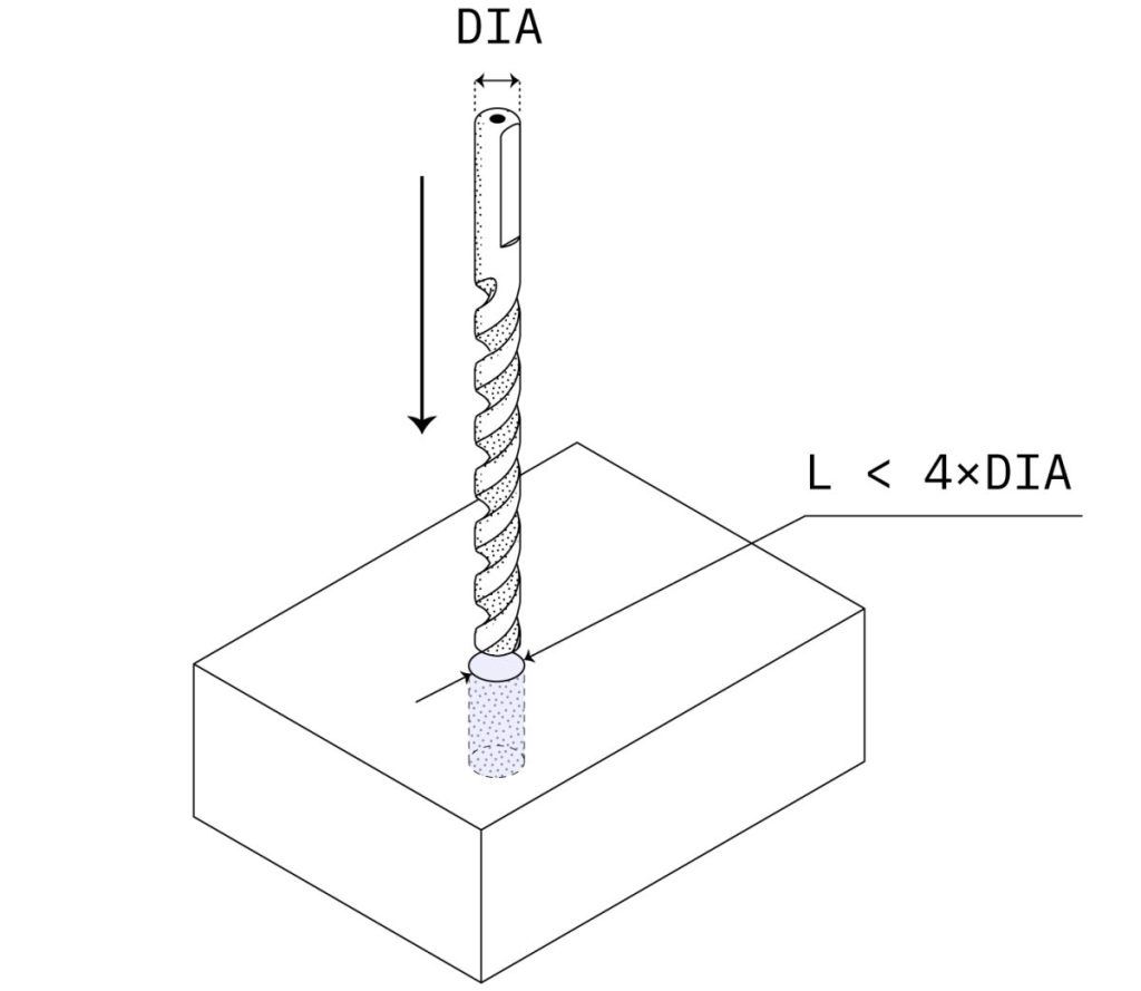
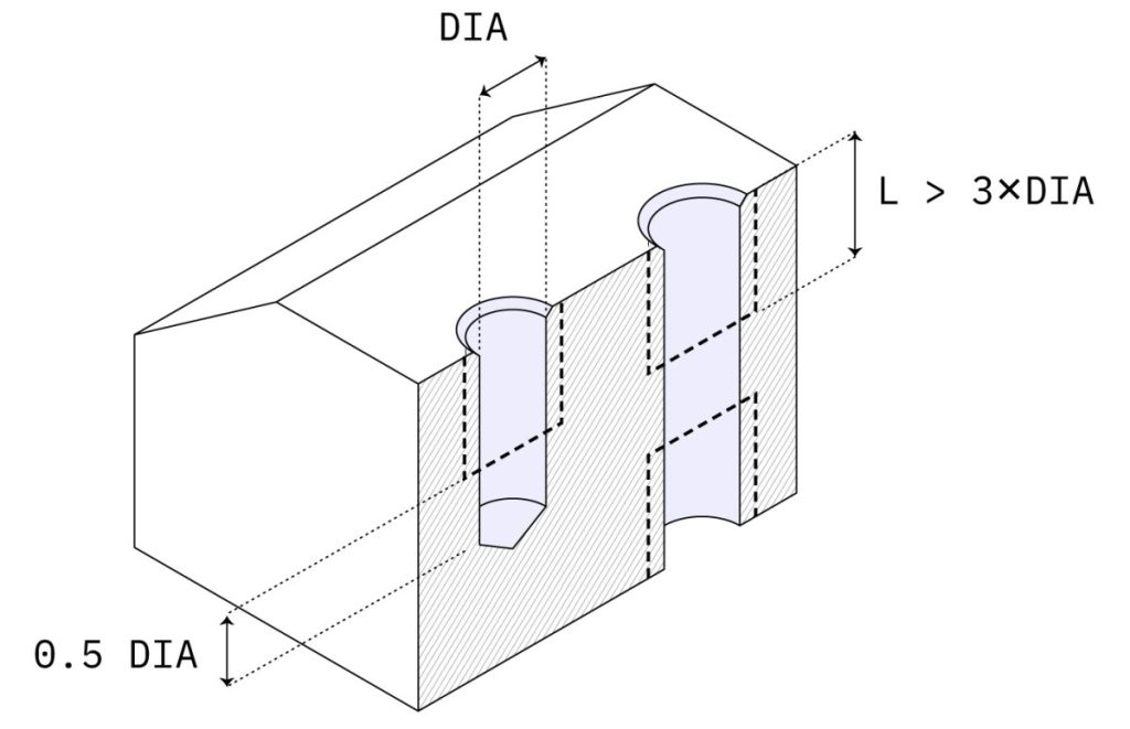
Holes
Recommended diameter: standard drill bit sizes
Recommended depth: 4 x nominal diameter
Max. depth: 10 x nominal diameter
Standard diameter holes are the preferred choice due to their compatibility with standard drill bits for machining. When a drill is used to machine blind holes, they will have a conical floor.
Non-standard diameter holes will be machined using an end mill tool and should be regarded as cavities (refer to the previous guideline). Blind holes machined with an end mill tool will have a flat surface.
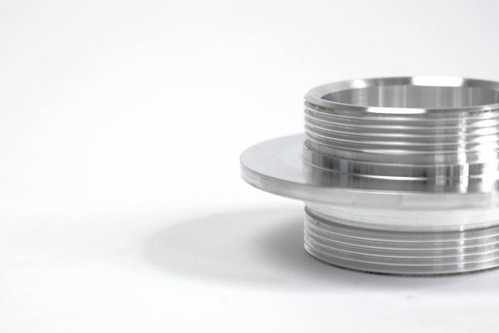
Threads
Recommended length: 3 x nominal diameter
Recommended size: M6 or larger
Feasible size: M2
Select the largest thread size available for easier machining. Threads exceeding three times the nominal diameter are deemed excessive.
Ensure that you consistently create threads as purely cosmetic elements within your CAD software, and remember to attach a technical drawing to your order.
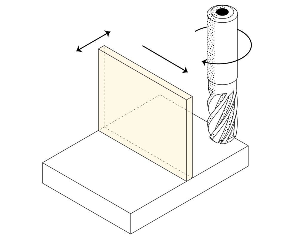
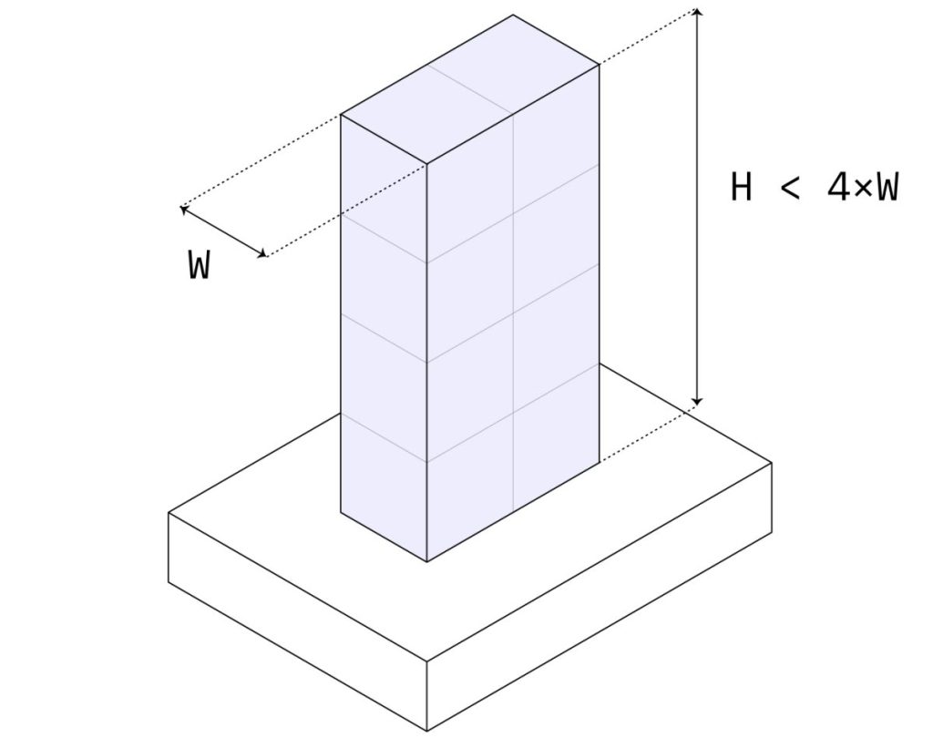
Tall features
Recommended max. ratio: height / width < 4
Machining tall features with precision can be challenging due to their susceptibility to vibrations. It is important to take into account the overall geometry of the part, as rotating it by 90° degrees during the machining process alters the aspect ratio.
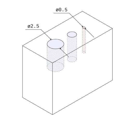
Small features
Recommended: 2.5 mm (0.100’’)
Feasible: 0.50 mm (.020’’)
Standard cutting tools can be used to CNC machine cavities and holes as small as 2.5 mm (0.1”). Any dimensions below this threshold are classified as micro-machining and should be avoided unless absolutely necessary.
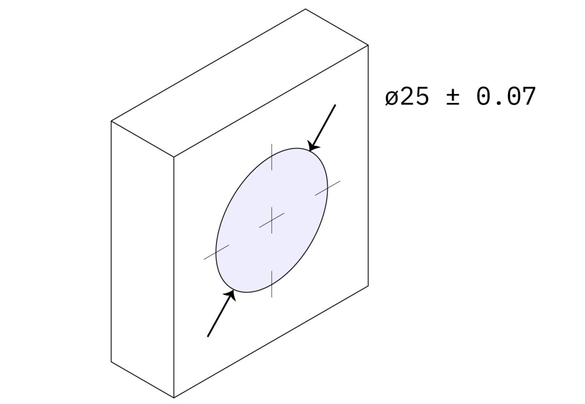
Tolerances
Standard: ± 0.125 mm (.005’’)
Feasible: ± 0.025 mm (.001’’)
It is essential to establish tolerances (unilateral, bilateral, interference, or geometric) for all crucial characteristics; however, it is crucial to avoid excessive tolerance.
If there is no tolerance specified in the technical drawing, the standard ± 0.125 mm will be maintained.
Maximum part size
CNC milling: 400 x 250 x 150 mm (typically)
CNC turning: Ø 500 mm x 1000 mm (typically)
Large CNC machines have the capability to manufacture components with measurements reaching up to 2000 x 800 x 1000 mm (78’’ x 32’’ x 40’’).
5-axis CNC machining systems generally possess a more compact construction capacity.
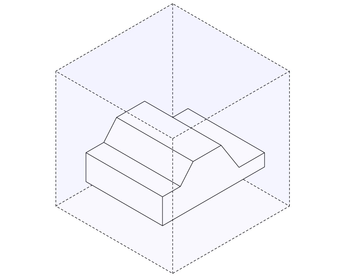
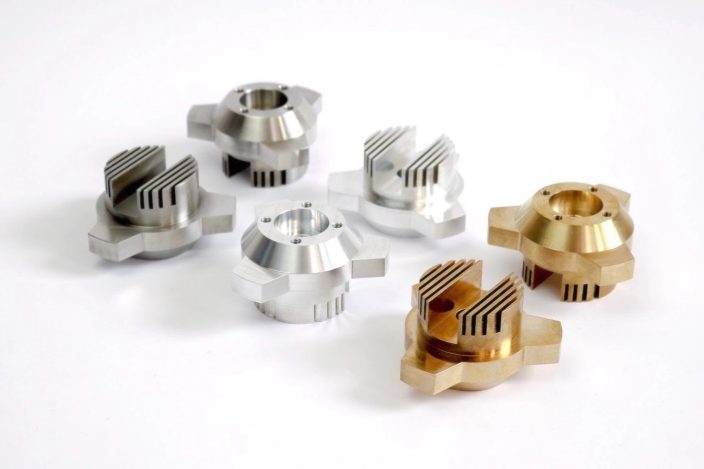
Designing undercuts
Undercuts are characteristics that cannot be fabricated using conventional tools, regardless of the part’s rotation, as the cutting tools are unable to reach all surfaces. In the case of square aluminum extrusions produced through CNC machining, the grooves present would be classified as undercuts.
Properly designed undercuts can be machined with specialized cutting tools in T-shaped, V-shaped, or lollipop-shaped configurations.
Below are a few useful recommendations to assist you in initiating the design process for undercuts.
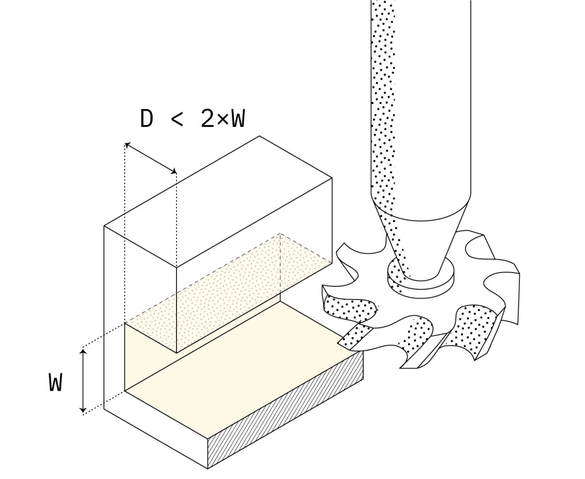
Undercut dimensions
Recommended width: 3 mm (1/8’’) to 40 mm (1 ½’’)
Max. Depth: 2x width
Create undercuts with a width that increases by one millimeter or follows a standard inch fraction. For undercuts with unique measurements, a specialized cutting tool will need to be made.
The cutting depth of the standard tools is typically around twice their width, which restricts the maximum depth that can be achieved.
Undercut clearance
Recommended min. clearance: 4x depth
Ensure there is sufficient clearance between the opposing walls to allow for tool access when creating undercuts on internal faces.
Part 3
Materials for CNC machining
Material choices
Choosing the correct material is an essential part of the design procedure. The most suitable material choice greatly relies on the particular use case and needs.
CNC provides a wide variety of material options to choose from, as almost any material with adequate hardness can be machined. In the realm of engineering applications, metals and plastics are the most pertinent and will be the main focus of this section.
Below, we will explore how surface finishes can modify the characteristics of CNC machined components.
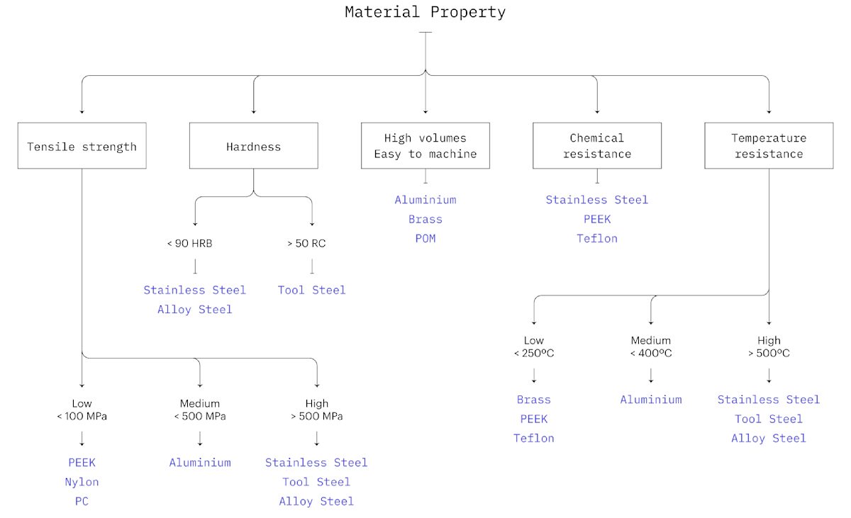
To commence, please refer to this decision tree. It encompasses top-level material suggestions that address the prevalent design prerequisites.
Part 4
Cost reduction tips

Tips to keep your CNC project on budget
The cost of CNC machined parts depends on the following:
- Machining time & model complexity: The greater the intricacy of a component’s geometry, the greater the time required for machining and the higher the cost associated with it.
- Start-up costs: The CAD file preparation and process planning are connected. They play a crucial role for smaller volumes, yet they remain constant. Leveraging economies of scale presents a chance to lower the unit price.
- Material cost & finishes: The overall cost is significantly influenced by both the price of the bulk material and the level of ease in machining that material.
As a rule of thumb:
In order to reduce the expenses associated with CNC machined parts, it is advisable to focus on designs that have uncomplicated geometries and standardized characteristics.
In the subsequent sections, we will revisit several design rules that were previously discussed, focusing on cost reduction. By implementing these three design tips, you will be able to significantly decrease the expenses associated with your CNC machined parts.
Tip #1: Increase the size of all fillets or add undercuts to sharp edges
In order to decrease machining durations, it is recommended to incorporate a fillet of maximum size to both internal and external vertical edges. By doing so, a larger tool can be utilized to eliminate more material in each pass, while also enabling a circular toolpath to be executed for faster cutting of corners.
When a 90° internal edge is required, decreasing the radius will not be sufficient. In such instances, opt for an undercut instead (refer to the information provided above).
To minimize cost:
- Add a radius that is slightly larger than 1/3 of the depth of the cavity.
- Add a small fillet also to external edges.
- Use undercuts when a 90° internal corner is required.
Pro tip: Use the same radius for all edges to save time on tool changes.
Tip #2: Minimize the number of machine orientations
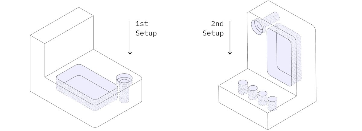
At least two machine setups are necessary for the upper section in a 3-axis CNC mill. Once the features on one side are machined, the workpiece needs to be manually rotated. This manual labor leads to an increase in costs.
On the other hand, multi-axis CNC machines can be utilized as an alternative. However, this option leads to a significant rise in machining expenses, ranging from 60 to 100%.
To minimize cost:
- Design components that can be manufactured in either one or two setups using a 3-axis CNC milling machine.
- If this cannot be achieved, contemplate dividing the section into several geometries that can be processed in a single setup and subsequently assembled.
Tip #3: Consider the cost of the material
Below is a summary table showcasing the expenses associated with CNC machining the same part using various commonly used materials. Each dollar sign represents an approximate 25% increment in price.
| Cost | Metals | Cost | Plastics |
|---|---|---|---|
| $ | Aluminum 6061 | $ | POM (Delrin) |
| $$ | Alloy steel 4140 | $$$ | ABS |
| $$ | Aluminum 7075 | $$$ | Nylon (PA 6) |
| $$$ | Brass C360 | $$$ | Polycarbonate (PC) |
| $$$$ | Stainless steel 304 | $$$$ | PEEK |
It is evident that opting for a material possessing physical characteristics that exceed the demands of your application can swiftly and needlessly escalate the expenses of your CNC machined components.
To minimize cost:
- Choose the material that offers the most cost-effective solution while meeting the necessary design specifications.
- Utilize online instant quoting services to promptly obtain pricing information for each material.
Part 5
Start CNC machining
Step 1: Export your design to a CNC-compatible CAD file format
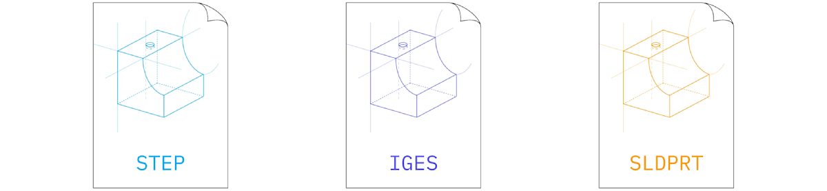
STEP and IGES are the primary file formats utilized in CNC machining. These formats are open-source, standardized, and compatible with various platforms.
For best results:
Transfer your designs seamlessly from your original CAD software to the STEP file format.
On XinYang, you have the option to upload files and receive an immediate quotation for file formats utilized in your native CAD software, such as SLDPRT, 3DM, IPT, SAT, and X_T.
Step 2: Prepare a technical drawing

A technical drawing may not always be necessary for machining parts with CNC. However, it is advisable to include one in your order as it contains additional information that is not provided in a STEP file.
A technical drawing is required in the following situations:
- In the event that your design incorporates threads.
- When specific tolerances are indicated.
- When specific surfaces require an alternative finish.
Step 3: Get an instant quote & start manufacturing
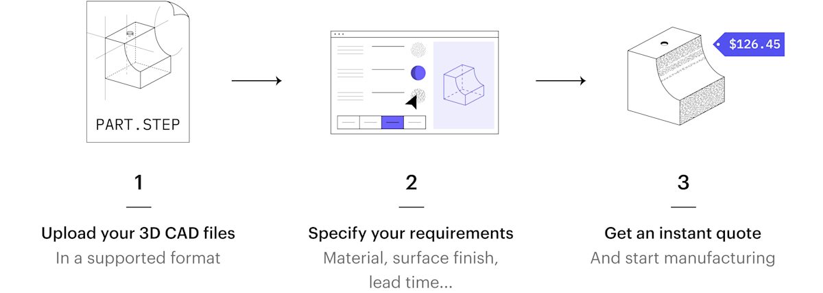
XinYang Network simplifies the process of outsourcing CNC machining parts, ensuring it is efficient, prompt, and offers competitive pricing.
Through the integration of a network of manufacturing services with our intelligent sourcing engine, you have the ability to immediately tap into existing production capacity for optimal quotes and lead times.
Once you submit your components to the Protolabs Network, our automated analysis for Machinability will identify any possible design concerns prior to commencing production. Subsequently, our machine learning algorithm will promptly provide you with a quotation.
Rest assured that by following this approach, you can guarantee that you will consistently obtain the most competitive prices in the market, along with the quickest turnaround times for your CNC machining parts.
Part 6
Useful resources
Knowledge Base
This guide covers all the necessary information to help you begin creating custom parts using CNC machining.
You can find a wealth of information on CNC machining in our Knowledge Base, which consists of technical articles covering various manufacturing technologies. These articles are authored by manufacturing experts and carefully selected by XinYang Network.
Below are some of our most sought-after articles on CNC machining:
Explore our blog, learn more about CNC, and get to know us