

…
A guide to thread types
.
Regardless of whether you are producing sheet metal, injection molded, or CNC machined parts, incorporating threads is an effective method to streamline the assembly process of various components.
Throughout numerous decades of production, threads have been standardized, allowing components from various manufacturers to be connected using standard fasteners.
Nevertheless, even though threads are universal, there exists a wide variety of types and sizes to select from. The choice of thread is influenced by various factors such as the thickness of the component, the angle of the joint, and the threading tools that are available.
This manual delves into the intricacies of threads and threading, covering the primary varieties of thread, optimal times for their usage, and techniques for their creation.
What are threads?
A thread is a spiral grooved formation that conforms to a cylindrical or conical form. In the field of engineering, a screw thread pertains to the spiral ridge found on either the screw (male) or the aperture where a screw is secured (female).
The purpose of a thread is straightforward: by rotating a screw, it advances into the hole, creating a secure connection between two components.
The process of creating threads for males or females is referred to as “threading.”
Thread series and types
Threads can be categorized based on their series or standard, as well as their type. The majority of threads are classified under either metric (M) or unified (UTS) standards.
Common series/standards include:
- ISO metric threads (M)
- Unified Thread Standard (UTS)
- National Pipe Threads (NPT)
- British Standard Pipe (BSPT)
- British Standard Whitworth (BSW)
- Glass Packaging Institute threads (GPI)
After the establishment of the thread standard, the specific thread type is determined by a numerical value or other variables, as explained in the subsequent section.
Anatomy of a thread
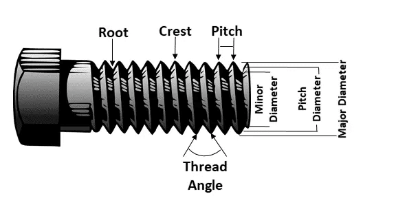
Threads may vary in several aspects, such as their diameter, pitch, and depth. It is essential to specify these factors when creating components with threads to guarantee proper fastening of all parts.
Aspects of a thread include:
- Thread size, also known as the nominal diameter or major diameter, pertains to the measurement of the widest part of the thread.
- The minor diameter refers to the smallest diameter between each ridge of a thread, representing its lower extreme diameter.
- The pitch refers to the measurement of the distance between individual ridges of a thread.
- Version 1: The lead refers to the length traveled along the screw’s axis during a single 360° rotation of the screw. It is distinct from the pitch, except in the case of multi-start / multi-entry threads.
- Thread depth indicates the extent to which a thread penetrates a hole.
- The taper of a thread refers to the extent to which the thread is conical rather than cylindrical.
Ways to make threads
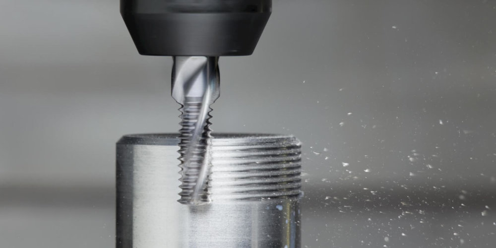
The majority of threads are created through subtractive, transformative, or occasionally additive methods.
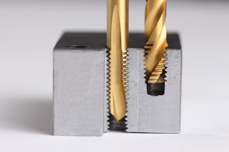
Subtractive threading methods encompass taps and dies, where taps form female threads and dies produce male threads; single-point threading, where a tool moves in a linear manner to create threads internally or externally; and thread milling, where a (CNC) mill is equipped with a cutting tool to create threads following a helical toolpath.
Techniques such as forming and rolling, which can be achieved through methods like using a fluteless tap, are utilized in transformative and deformative threading processes. Rolling techniques may manifest as flat die thread rolling, planetary thread rolling, two-die cylindrical rolling, or three-die cylindrical rolling.
Additive methods involve the direct printing of threads onto 3D printed components. Nevertheless, only advanced systems can achieve the necessary precision and tight tolerances for accurate thread production.
Blind holes and thru holes
There are two distinct categories of thread holes: blind holes and thru holes. Blind holes are characterized by having an entry point but no exit point, as they do not fully penetrate the part. On the other hand, thru holes extend all the way through the part, with their depth matching that of the corresponding section.
Design tips
Creating components with threads may not be complex, yet it necessitates precision to facilitate manufacturing. Threads can be formed directly in certain instances (such as through 3D printing); alternatively, they can be added post-fabrication by drilling holes.
Guidelines to follow include:
- Version 1: Familiarize yourself with the standards (and adhere to them): Unless there is a valid justification, it is advisable to adhere to the widely used series (UN or M) and standard sizes whenever possible. In cases where you need to slightly adjust the thread size to accommodate a standard size, it is often beneficial to make that compromise.
- When creating blind holes, it is important to note that the thread depth should be less than the thickness of the wall being threaded. To ensure accuracy, the precise depth must be specified in the CAD design and/or any technical drawings.
- Understand your boundaries: Thread depths are constrained by factors such as thread diameter, material, and threading tool. Over-specifying a thread depth may result in part failure or the manufacturer being unable to carry out the design.
- Utilize CAD software equipped with threading tools to streamline the process. Designing threads becomes more efficient with a CAD/CAM solution that provides optimized tools for thread design.
XinYang specializes in prototyping and possesses extensive knowledge in various manufacturing processes. Feel free to reach out to us for a complimentary quotation.