
Design Guidelines for CNC Milled Parts
.
Just like with any other manufacturing process, CNC milling necessitates the meticulous implementation of design for manufacturing (DfM) principles. While CNC mills, and 5-axis machining centers even more so, have the capability to create a diverse array of parts using various metals and plastics, it is essential to adhere to specific design limitations to ensure the production of functional parts.
Designing components for CNC milling is distinct from designing components for injection molding or extrusion. It also varies from the design of CNC turning components. Consequently, CAD specialists must acquaint themselves with the tangible constraints of the procedure prior to creating parts that are impractical to manufacture.
Luckily, the design principles for CNC milled components are quite straightforward. As long as these principles are adhered to, your components will successfully pass inspection.
What is CNC milling?
CNC milling stands out as a primary method of CNC machining, alongside CNC turning and drilling. The distinctive feature of CNC milling lies in the utilization of rotary cutters with sharp edges to eliminate material from the workpiece. In contrast, CNC turning revolves around rotating the workpiece, while drilling is specifically employed for creating holes.
Milling machines offer a vast array of possibilities due to the extensive selection of cutting tools available. Various tools such as end mills, face mills, and fly cutters serve distinct purposes, enabling machinists to execute a diverse range of cuts on the workpiece.
CNC milling design constraints
There are several crucial factors that dictate the acceptability of a design when it comes to CNC milling. These factors encompass the machine setup or workpiece orientation, the configuration of the cutting tool, the cutting tool’s length (i.e. its ability to penetrate the workpiece), and the material of the workpiece.
Workpiece orientation
One important factor to take into account in CNC milling design is the setup of the machine or how the workpiece is secured to the worktable. Due to the necessity of fixing the workpiece to the worktable, a portion of it becomes unreachable by the machine tool, requiring machinists to carefully plan the orientation of the workpiece.
Milling parts with features on only one face is easier because the side without features can be placed downwards, allowing the machine tool to reach the side with features. On the other hand, parts with details on all sides need multiple setups: after milling one side, the workpiece must be removed from the workholding devices, flipped, and then milled on the other side.
Designers should aim to create parts that can be milled with minimal setups, as each additional setup necessitates time and calibration, ultimately contributing to the overall cost of the part.
Tool geometry and diameter
The shape and size of the cutting tool in CNC milling have a distinct impact on part design. Two crucial factors need to be taken into account. Firstly, due to the continuous rotation of the cutting tool, it produces a circular cut. Consequently, milling square inside corners becomes unattainable. This limitation can be likened to a circular Roomba vacuum cleaner’s inability to clean the corners of a rectangular room. The geometry of the tool does not align with the surrounding space, resulting in this mismatch.
The design of a part is also constrained by the diameter of the cutting tool. It is not possible for a cutting tool to create a cavity that is smaller than its own diameter. Therefore, although larger tools are effective in removing large amounts of material, they are unable to achieve intricate details.
Tool length
The tool depth is a crucial design constraint in CNC milling, determining the maximum depth the cutting tool can penetrate into the workpiece. While it may seem that any hole depth can be achieved with a sufficiently long tool, it is important to consider the impact of tool length on the milling operation. Longer tools are more prone to generating chatter, an unwanted vibration that compromises the precision of the milling process.
Workpiece material
Various metals and plastics exhibit varying degrees of machinability, which refers to the ease with which they can be cut by the CNC mill without causing deformation or damage to the cutting tool.
In the process of CNC milling design, it is crucial to take into account the machinability of the material, particularly when aiming for precise tolerances and intricate features. For instance, when comparing a component crafted from aluminum 6061 to one made from a tougher metal such as stainless steel 440, the former may allow for deeper holes and attain a more stringent dimensional tolerance.
CNC milling design guidelines
We have examined several constraining elements that dictate the approach to CNC milling part design. Presently, we will delve into a set of CNC milling design principles and guidelines to adhere to, taking into account these factors. These encompass incorporating rounded corners, determining cavity depth, and establishing a minimum wall thickness.
Part size
CNC milling part design must take into account the maximum part size, which is dictated by the work envelope of the CNC mill in use. To provide an example, Haas, the manufacturer of XinYang’s largest 3-axis milling machine, offers a work envelope measuring 1016 x 508 x 635 mm. Nevertheless, it is worth noting that numerous mills are considerably smaller than this.
Additionally, it is important to consider that 5-axis machines typically have more limited work envelopes compared to 3-axis mills, which could restrict the ability to incorporate numerous off-axis features with exceptionally large dimensions.
Align features
Due to the investment of time and resources required for setting up the workpiece repeatedly, designers are advised to consolidate features such as holes and vertical walls on a single face. This approach enables the machinist to efficiently mill all the necessary features of the part in one setup.
A 5-axis machining center offers versatility for off-axis features and holes, allowing the cutting tool to approach the workpiece from various angles without the need for a new setup.
Radii

Designers must keep in mind that due to the circular shape of cutting tools, it is not feasible to create square inside corners without employing intricate undercuts. Consequently, internal corners will have a rounded shape, with the radius size being dependent on the tool’s diameter.
With that being stated, employing an internal corner radius marginally greater than the tool radius will yield superior outcomes, as it provides ample clearance for the tool to navigate the corner.
Furthermore, by designating an identical radius for every internal corner, the milling process can be expedited.
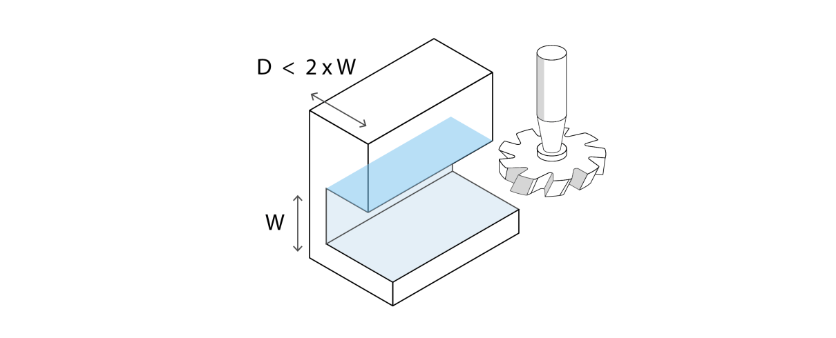
Cavity depth
In order to reduce excessive noise, tool deviation, and other complications, milled components are restricted to having cavities with limited depth. As a general guideline, the depth of these cavities should not exceed four times their width.
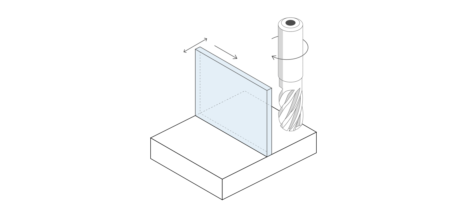
Wall thickness

It is recommended that designers do not specify a thickness lower than 0.8 mm for metals or approximately double that thickness for plastics when CNC milling thin walls, such as part-strengthening ribs.
Moreover, it is recommended that the height of these slender partitions should not exceed 10 times the thickness of the wall. For instance, a wall with a thickness of 5 mm should have a maximum height of 50 mm.
Holes and threads

Designers are encouraged to indicate holes and threads with diameters that align with standard drill bits and threading tools whenever feasible. While it is possible to use non-standard diameters, they would require the use of an end mill tool for cutting.
It is crucial to take into account both the width and depth of the hole. Generally, the depth of the hole should not exceed approximately 10 times its diameter. However, it is possible to create deeper holes using specialized drill bits.
The foundation of a blind hole, which does not completely penetrate the workpiece, will solely be level if it is carved using an end mill. However, if a drill bit is used, the base will have a conical shape.
Lettering
Engraving is a more efficient method for adding text to the surface of CNC milled parts compared to embossing, as it requires less material removal. Additionally, milling rounded sans serif fonts is considerably easier than working with decorative fonts.
When working with hard metals, it is recommended to use a font size of no less than 20. On the other hand, softer metals and plastics can easily accommodate a font size of 16.
Tolerances
Designers must take into account realistic tolerances when designing parts for CNC milling. The standard tolerance is 0.1 mm, however, it is possible to achieve tighter values, reaching as low as 0.01 mm. Nevertheless, it is important to note that achieving these tighter tolerances may require additional time and cost. For more information on tight-tolerance milling, we invite you to explore our precision machining services.
CAD software for CNC milling design
Many CAD programs are capable of creating designs for CNC milling. Nevertheless, the industry commonly relies on the following two software packages.
SOLIDWORKS
SOLIDWORKS, created by Dassault Systemes, is a full-featured CAD software that includes functionalities for verifying CNC milling blueprints.
The widely used CAD software includes DFMXpress, a Design for Manufacturability (DfM) tool that allows users to define milling constraints specified by the manufacturer, such as the maximum ratio of hole depth to diameter. Additionally, this tool can identify non-machinable features, highlighting any areas that cannot be accessed by the cutting tool and bringing them to the user’s attention.
Fusion 360
Fusion 360, created by Autodesk, is a popular choice among engineers and machinists due to its numerous features designed specifically for CNC machining.
Like other CAD packages focused on CNC, Fusion 360 enables the use of both general and user-defined constraints to ensure that the design does not include any features that cannot be milled. Additionally, as a CAM tool, Fusion 360 has the capability to generate toolpaths specifically for CNC mills. However, if the design is not feasible, the software will be unable to create these toolpaths.
CNC milling with XinYang
XinYang possesses extensive expertise in operating CNC milling equipment and is capable of transforming your designs into top-notch machined components. Moreover, you can rest assured about minor design flaws as well. Once you upload your CAD files, we will conduct a DfM analysis, if required, and provide you with valuable insights to enhance your design until it becomes suitable for manufacturing.